
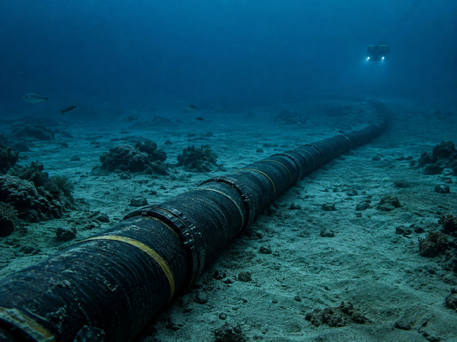
When a message crosses an ocean, the journey is usually less cinematic than a satellite beam but far more tangible: a sequence of glass fibres laid on the seabed, joined at stations on land, and connected at each end to the networks that carry data through cities and buildings. Submarine telecommunication cables form a physical bridge between terrestrial networks. They carry the information that people experience as a website, a cloud file, a video call or a financial transaction, but the cable itself is only one part of a much larger system. The route, landing facilities, power equipment, inland connections, maintenance arrangements and alternative paths all matter.
The International Telecommunication Union (ITU) describes submarine cables as carrying approximately 99% of the world’s Internet traffic. That figure is an estimate of the central role of cables in global communications, not a claim that every local connection or every data path travels beneath the sea. A message sent between two devices in one city may remain on land; a satellite may serve places where cable access is limited. But when networks need to exchange large volumes of data across oceans, cables are the high-capacity workhorses. This article follows their path from a question typed on shore to light travelling through glass under water, then looks at how the route is built, protected, repaired and made more resilient.
From a user’s request to a route across the ocean
It is useful to begin with what a submarine cable does not do. It is not a separate Internet, and it does not make decisions about where a web page should go. Internet protocols, routers, operators and applications determine how information is addressed and forwarded. A submarine cable is one of the physical links available to those networks. At the shore, a provider’s terrestrial network carries data to a cable landing station. The station’s equipment sends the optical signal into the submarine system. At the far end, another station receives it and hands it to terrestrial networks, which carry it onward.
A user rarely knows which physical cable carried a particular packet. Internet traffic is divided into packets, and networks can make routing decisions based on connectivity, congestion, policy and available capacity. Different packets in one conversation may take different paths, and paths can change when equipment or links are unavailable. The undersea route therefore sits inside a changing network rather than acting like a single private wire from one person’s phone to another’s computer.
The demand for a cable begins with a need for capacity and connectivity between places. Operators, telecommunications companies, cloud and content providers, and sometimes governments or other investors may participate in a system. Older projects often relied on consortia of carriers; private systems also exist, and ownership models have changed over time. A cable’s owners decide how to finance it, what capacity to equip at first, how to sell or use capacity, and how to coordinate with other networks. A route on a map is not just a line drawn between two cities: it represents a set of landing points, permits, marine surveys, engineering choices and long-term operating responsibilities.
Why light through glass is suited to long distances
Modern submarine telecommunication systems use optical fibres: very thin strands of glass that guide light. At a transmitting terminal, equipment converts electrical information into an optical signal, using a laser to encode changing patterns of light. The glass core guides that light along the fibre. At the receiving end, optical equipment detects the arriving signal and converts it back into electrical form for the network equipment on land. Digital systems interpret the changes according to their transmission design; a fibre does not carry a picture of a web page or a stream of understandable words.
The glass core is surrounded by additional layers that help guide light and protect the fibre. A modern cable may contain multiple fibres, grouped in pairs and arranged within a carefully engineered structure. A fibre can be much finer than a human hair, while the complete cable, especially near shore where it needs added protection, is much thicker. The image of a garden hose is a useful rough comparison for many deep-water cables, but cable dimensions vary with design, depth and protection needs. A cable’s external appearance should not be confused with the size of its optical pathways: the communications capacity resides in the fibre and the terminal equipment, not in a single large hollow tube.
Optical systems can carry many signals at once. In wavelength-division multiplexing, different optical wavelengths are combined so that multiple channels can travel through a fibre and be separated again by equipment at the ends. This is a way of using the available optical medium more efficiently. It does not mean that every cable carries an unlimited amount of data, or that the theoretical capacity is already in service. TeleGeography distinguishes potential capacity, which reflects what might be possible with equipment installed, from lit capacity, the capacity actually activated and used. Owners can increase the equipped capacity over time as demand and economics justify upgrades.
Light loses strength as it travels. To carry signals over long oceanic distances, cable systems use repeaters or optical amplifiers along the route. Their spacing depends on the system design; figures such as roughly 50 to 80 kilometres appear in technical descriptions, but there is no single spacing rule for every cable. Repeaters amplify the optical signal so that it can continue along the route. They are part of an engineered system that also needs power, monitoring and careful installation. Shorter routes may not need the same arrangement as long transoceanic systems.
Inside the cable: a system, not just a fibre
A submarine cable system includes more than the fibre bundle resting on the seabed. It commonly links two or more onshore terminal or cable landing stations. The station equipment transmits and receives signals, manages the optical line and connects the submarine line to terrestrial networks. Between stations, the cable can include optical repeaters and, where a route serves several destinations, branching units. A branching unit gives a system a way to connect to additional landing points; it is not simply a loose junction, but a designed component of a network topology.
Many systems include a conductor and electrical insulation so that power can be supplied from shore to submerged equipment such as repeaters. This does not mean the cable is an ordinary electrical power line for households. Its principal purpose is telecommunications; electrical power in the cable system supports the line’s own equipment. The details depend on the system architecture. That distinction helps explain why cable engineering involves both optical transmission and electrical design, as well as the mechanical strength needed for deployment and recovery.
The outer layers vary according to where the cable will lie and what hazards are expected. In deep water, a lighter construction may be appropriate because the cable is less exposed to anchors and fishing gear. In shallower waters, extra steel-wire armouring may be added. Near the coast, operators may bury cable below the seabed or use other protective arrangements, because human marine activity is more concentrated there. These are general patterns, not guarantees for every location: exact design and placement depend on surveys, local conditions, seabed characteristics, regulations and the cable owner’s engineering choices.
Protection is a balance. More armour can improve resistance to certain kinds of external contact, but it also affects weight, flexibility, handling and deployment. A cable must be strong enough for the intended installation and robust enough for its operating environment, while remaining suitable for a ship to manage and a repair team to recover. The bending radius matters: optical fibres and cable structures have limits, and severe bending can damage a system even if the cable is not visibly severed. The science of a cable is therefore not confined to transmission; materials and mechanical behaviour shape whether light can keep travelling safely.
Planning the route before the ship sails
A route is selected through studies that combine network needs with marine geography. Planners consider where landing stations can be built, how a route can connect to inland networks, and whether the proposed sea path can be installed and maintained. Marine surveys help identify the seabed’s shape and composition, obstacles, geologic features and areas where a cable might be exposed to damage. The goal is not to find a perfectly risk-free line; no long route can eliminate every hazard. Instead, operators and engineers seek a feasible path and a design that reduce foreseeable risks while meeting technical and commercial requirements.
Environmental and regulatory review is also part of the project. A cable may cross waters under different national jurisdictions or international rules. Shore approaches require land access and construction planning. The project may need to coordinate with maritime users, port authorities, environmental regulators and other infrastructure operators. The process can take years; the ITU notes that a submarine cable can take more than two years from design to operation, with funding, permits, regulatory coordination and environmental requirements all influencing the timeline. A cable shown as planned on a map is not necessarily already installed or carrying traffic.
At sea, specially equipped cable ships carry the cable in large tanks or holds, where it is coiled in a controlled way. The vessel follows a surveyed route and pays out cable at a managed speed and tension, while navigation and positioning systems help align it with the plan. Near shore, the installation method may include a plough or other equipment to place the cable in a trench, or a controlled approach from a landing point. In deeper water, cable may be laid directly on the seabed. The exact operation depends on water depth, seabed and local conditions. Cable ships do not simply drop an unplanned coil from the surface and hope it lands in the right place.
Installation is a sequence of linked steps: survey, route engineering, permits, manufacture, mobilization, landing-site preparation, cable loading, laying and testing. The cable is checked as it is installed, and the ends are connected to equipment at the landing stations. The route’s final shape may include slack or design adjustments needed for seabed conditions. Maintenance planning begins before service starts, because a repair vessel, spare cable, compatible equipment and trained personnel must be available if a fault occurs later.
Landing stations connect sea routes to everyday networks
A cable landing station is a controlled facility at the coast where the submarine line reaches land and connects to terrestrial communications equipment. It may house transmission and reception equipment, line management systems, power-feeding equipment and links to inland networks. The cable’s path does not end at the beach: the station must connect onward to a provider’s network, data centers, exchange points or other infrastructure. Some major network facilities may be far from the shore, so inland fibre routes are another important part of the total journey.
That coastal transition can be one of the more exposed parts of a system. Near shore, anchors, fishing, dredging, construction and other marine activity are more common than in remote deep water. Cables may be buried or armoured to reduce some risks, but no protective method makes them invulnerable. The cable route and landing station need coordination with local infrastructure, because a well-designed ocean crossing will not provide useful resilience if the access path on land is itself a bottleneck.
Landing points also influence the network’s topology. A route with several landing points can connect more places, sometimes through branching units. However, more connections do not automatically mean more resilience. If several systems converge on the same coastal corridor, station, inland duct or power source, a local incident could affect more than one nominally separate cable. Network designers therefore pay attention to the whole path from one network node to another, not simply the number of lines drawn on an ocean map.
For users, the landing station is usually invisible. A service provider may not reveal which exact cable carried a particular request, and that information is not needed for ordinary browsing. But knowing that the station exists helps explain why a cable is infrastructure: it must be connected, powered, monitored and operated by people and organizations on shore as well as at sea.
How faults are found and repaired
Submarine cables are designed for long service and are monitored by the systems that operate them, but faults still occur. Causes include accidental human activity such as fishing gear or anchors, as well as natural events such as seabed movement, earthquakes, underwater landslides or abrasion. The proportions vary by dataset, time period and depth. ITU’s April 2026 backgrounder reports more than 170 cable repairs worldwide in 2025, citing the International Cable Protection Committee; that is a count of reported repair events, not a prediction that any specific cable will fail or a measure of how much traffic was lost. TeleGeography’s FAQ similarly notes that fishing and dragging anchors account for a substantial share of faults and that deliberate sabotage and shark bites are rare compared with common accidental causes.
When equipment detects a fault, network operators and cable-station staff run tests to narrow down its location. Tests can estimate the distance along the cable to a problem; engineers then combine this with route charts and operational information to plan a repair. A repair ship has to be available, equipped with the right cable, tools and splicing facilities, and able to reach the site under suitable weather and marine conditions. Repairing a line is not like plugging a connector back in on a desk. Locating and recovering a cable from the seabed can be a major marine operation.
On a repair voyage, a cable ship may use grapnels or remotely operated vehicles, depending on conditions and burial. The damaged section is recovered, inspected and cut out as needed. Cable ends are brought aboard, tested and prepared; a replacement section may be spliced in. The splice is checked, then the repaired cable is lowered back to the seabed. If the cable was buried, the repaired segment may need to be reburied. Each step must preserve the optical path and the cable’s protective structure. A repair can take many days, and weather, depth, location, shipping and access all influence how long it takes.
Even a successful repair may leave a changed route geometry or a splice that operators need to record and protect. A cable system’s documentation is essential: repair crews need accurate route information, the correct spare components, system test data and a clear understanding of prior repairs. The expertise of crews, operators, equipment suppliers and marine contractors is part of the resilience story. Resilience is not only the ability to avoid a fault; it is also the ability to detect it, mobilize an appropriate response and restore service without unnecessary delay.
Why route diversity matters—and what it cannot guarantee
Network resilience often depends on having more than one path between important places. If a cable fails, network operators may redirect traffic over other cables or terrestrial links. That can keep some services available, although users may still notice higher latency, congestion or reduced capacity. The alternative path must have enough spare capacity, must connect to the relevant networks, and must not share the same vulnerable segment or landing infrastructure. Two lines on a map may not be truly independent if they follow the same corridor or converge at the same station.
Geographic diversity is one tool. Routes that cross the ocean in different places, land at different points and connect to different inland networks may reduce the chance that one local hazard disrupts all paths. But diversity has cost and practical limits. A new cable needs investors, permits, surveyed routes, landing facilities, maintenance agreements and enough demand to justify construction. Some locations have only a small number of feasible coastal approaches. A route that seems geographically separate at sea might still rely on the same local power, exchange, road or fibre corridor after it reaches land.
Capacity planning also matters. A backup route that exists but is already full may not absorb traffic from a major failure. Operators can design systems with spare capacity or arrange capacity on other networks, but those arrangements have technical, commercial and operational constraints. The existence of another cable does not, by itself, prove that every affected service will switch instantly or without interruption. Networks use traffic engineering and routing protocols, but recovery performance depends on what has been prepared and tested.
ITU’s resilience work emphasizes cooperation, better identification of risks, repair readiness and improved deployment and maintenance practices. These themes connect public authorities, cable owners, service providers, marine industries and technical organizations. A strong system combines route diversity, sound engineering, effective monitoring, maintenance planning, available repair resources and realistic capacity. No single measure eliminates risk. The practical goal is to limit the chance and impact of failures, and to shorten restoration time when one does occur.
Environmental care and shared use of the seabed
Submarine cable routes share the ocean with ecosystems, fisheries, shipping, energy projects, scientific surveys and other infrastructure. Route planning and installation therefore need to consider local marine environments and existing uses of the seabed. Environmental review can affect where a cable is laid, when work occurs, how a shore approach is built and what mitigation is appropriate. A cable project is not automatically harmless because most of its length is underwater, nor is every cable route environmentally identical. The context matters: depth, habitat, construction method, local law and nearby activities all shape potential impacts.
Burial and armouring are primarily engineering responses to exposure, but they also interact with the seabed. A plough or water-jetting operation changes a narrow corridor during installation or repair. The significance depends on the place and method; it should be assessed using project-specific evidence rather than broad assumptions. In some areas, a cable can be laid directly on the deep-ocean floor, while near shore it may be buried where practical. Monitoring and coordination with marine users can help reduce damage and avoid conflicts.
The cable industry also shares information about cable locations and safe practices with fishing and shipping communities. This can help reduce accidental contact, especially where vessels work near routes. Maps and notices are not substitutes for safe navigation or local regulation, but they support awareness. Operators and authorities may coordinate on route information, marine planning and repair access. The broad idea is simple: the seabed is a working and ecological space, and infrastructure planning is better when different users understand how their activities overlap.
What a cable outage feels like to people
A cable failure does not necessarily mean an entire country loses its Internet. The result depends on which routes are affected, how networks are connected, how much traffic they carry, whether alternatives are available and how much spare capacity exists. Some users may experience slower connections, higher latency, disrupted international services or trouble reaching particular networks. Others may see little change because their traffic uses another path or because local services remain reachable through domestic infrastructure. The same event can therefore have different effects across providers and regions.
Latency is the time it takes data to travel and return, and distance matters: a signal cannot cross an ocean instantaneously. Fibre routes can offer lower latency than some satellite paths for many long-distance links, but actual performance also depends on route length, network equipment, congestion and service design. Cable maps show physical routes and landing points; they do not tell a reader exactly which path a particular application uses at a particular moment.
When news reports say a cable was damaged, it is useful to separate confirmed facts from interpretation. A reported break does not by itself establish why it happened, who was responsible, or which services will be affected. Operators may need time to inspect equipment, locate the fault, estimate traffic impact and arrange repairs. Public statements can be incomplete while those processes are underway. Responsible reporting distinguishes an observed outage or repair from a cause that has not yet been established.
Satellite links and cables serve different roles
Submarine cables and satellites are sometimes presented as competitors, but they often address different connectivity needs and can complement one another. Fibre cables carry high volumes of traffic along fixed routes between landing points. Satellites can provide links where terrestrial or cable infrastructure is unavailable, and can support mobility or remote access. Each technology has different capacity, latency, coverage, cost and operational considerations. A satellite does not remove the need for cables in high-capacity oceanic networks, and cables do not make satellite services unnecessary.
For a user, the relevant question is not whether one technology will replace the other everywhere. It is how multiple forms of connectivity fit together for a particular region, application and risk. A remote island may depend on a small number of cable routes, satellite links or both. A global cloud service may use submarine cables for intercontinental exchange and satellites for specific access cases. Redundancy is strongest when different paths have genuinely different failure modes and adequate capacity, not simply when a second technology is named.
A changing network, upgraded over time
Submarine cable technology evolves as demand grows and equipment improves. The cable itself is installed for a long operational life, while terminal equipment at the ends can be upgraded or expanded. This distinction helps explain how operators can increase a system’s usable capacity without replacing every metre of seabed cable. New optical equipment can exploit more of the fibre’s potential, subject to the design limits of the installed system and commercial decisions about which upgrades are worthwhile.
More data demand does not mean that every cable instantly reaches its maximum capacity. TeleGeography’s explanation of lit and potential capacity is a reminder that the hardware and the active service are not the same thing. Owners may equip a route gradually. Capacity can also be affected by the number of fibre pairs, the optical design, repeaters, terminal technology and network agreements. Comparisons between cable systems need to specify what is being compared: theoretical design capacity, equipped capacity, lit capacity or traffic actually carried.
Growth also brings new challenges. More systems can create more route options, but construction is expensive and requires coordination across jurisdictions. A network that depends on a few heavily used corridors can remain vulnerable even if the global map looks dense. New investment may therefore be driven not only by demand but also by resilience, geographic diversification and access to underserved areas. These choices involve engineering and public policy as well as market economics.
How to read a submarine-cable map carefully
Public cable maps can make the global network easier to understand, but the map is a guide, not a live traffic dashboard. A line may represent a planned or active system, and datasets may be updated at different times. Landing points and route geometries can be shown at a level of detail suitable for public information, not necessarily the precise operational route. A map does not reveal current capacity, contractual arrangements, traffic routing or the status of every component.
When comparing maps or statistics, check the date and the definition. Does the count include planned cables or only systems in service? Is a length measured for one cable segment or an entire system with several landings? Does “capacity” mean potential or lit capacity? Are fault figures based on a single year, a historical period or reports from a particular set of operators? Clear definitions make the numbers more useful and prevent a broad estimate from being mistaken for an exact measure.
TeleGeography’s cable map describes system names, ready-for-service dates, lengths, owners, landing points and related information. Such data can help explain how the network is arranged, but it should not be used to infer that two paths are operationally independent without looking at their land routes and shared facilities. Likewise, the presence of a cable on a map does not prove that it is available for every service or that it has spare capacity at a given time.
Why cooperation is part of the technology
A cable crosses boundaries: between land and sea, between national jurisdictions, and between technical and commercial responsibilities. A system’s resilience depends on the ability of different organizations to coordinate. Cable owners need maintenance agreements and repair arrangements. Governments and regulators need processes for permits and emergencies. Marine users need reliable information to reduce accidental damage. Network operators need to understand how alternatives connect and where capacity is available. International organizations can help establish shared technical guidance and convene participants around common problems.
The ITU and International Cable Protection Committee have promoted work on submarine cable resilience. The ITU’s April 2026 backgrounder describes priorities such as improving protection, streamlining maintenance, addressing accidental human activity, speeding recovery and encouraging sustainable practices. These are not a substitute for national laws or each operator’s engineering decisions. They provide a framework for cooperation around infrastructure whose operation depends on many actors.
Good public understanding matters too. Overstating a cable’s role as “the whole Internet” can obscure the terrestrial networks, data centers, routers and local access links that also carry information. Understating it can hide how much international connectivity relies on a relatively small number of physical routes and landing facilities. A balanced picture recognizes the undersea cable as one crucial layer in a larger system.
The journey in one picture
Imagine a request that begins in a home or office. A local connection carries it to an Internet provider. Routers pass it through terrestrial networks toward a cable landing station. There, optical terminal equipment encodes the data in light and places it on a fibre pair. Repeaters along a long route restore the signal. The cable crosses the seabed, with its construction and placement adapted to depth and hazards. At the other landing station, equipment receives the light and connects the data to another terrestrial network. Routers then carry it to the service or destination. Replies travel back through a path chosen by the networks; it may be similar or different.
Every stage has its own limits and failure modes. A cable may be intact while a landing station or inland link has a problem. A damaged cable may be bypassed if another route exists and has capacity. A repaired line may still require testing and traffic to be restored. These distinctions are why an undersea cable should be understood as part of a system rather than a magic wire that alone “is the Internet.”
The system’s success is quiet: a user taps a button and the ocean does not enter the conversation. Behind that ordinary moment are optical physics, carefully engineered materials, marine surveys, cable ships, landing stations, network protocols and repair crews. The technology is impressive not because it abolishes distance or risk, but because it makes reliable high-capacity communication across distance possible through layers of design, maintenance and cooperation.
Sources and evidence notes
This overview draws on technical and public-interest material from the U.S. Congressional Research Service, the International Telecommunication Union, TeleGeography, and the KIS-ORCA subsea-cable information project. Figures on traffic share, cable counts, system length and repair totals are dated estimates and can change as systems enter service, retire or are newly reported. Technical details vary between cable systems; examples of repeater spacing and construction are not universal specifications.
- Congressional Research Service, Undersea Telecommunication Cable Systems
- International Telecommunication Union, Submarine cable resilience (last updated April 2026)
- TeleGeography, Submarine Cable FAQs
- KIS-ORCA, Design
- KIS-ORCA, Maintenance / Repair Operations
This content is a collection of ancient history,books and various articles and collection of library and news and other post ; all details may not be the same. Readers are requested to verify the information themselves. Readers are not allowed to take any disciplinary action; content is only for educational purposes. If readers do not agree about the contents, they may send a personal comment to my personal email ID: achary.purna@gmail.com
